Engineering Projects
Solar Array Drive Assembly
Purpose
As exploration gets further from Earth, it becomes increasing difficult to gather solar energy from the sun. Our team's aim is to design a mechanical joint that allows the solar panels of a 6 unit CubeSat to face the sun at all satellite orientations, thus allowing it to collect maximum power from the sun.
Process
Our team went through standard design phase to get to the final product. Because our biggest constraints were size and a limited budget for a space project, much of the design centered around the smallest parts we could get off the shelf. In this case the 8mm stepper motors and the bevel gears paired with our bounding box drove the dimensions of the design. After fabricating parts from Protolabs, we analyzed how our design would hold up against expected hazards and provided adjustments and suggestions for the next iteration.
Results
Our final results were a prototype and an analysis into several aspects of our design. As seen in the video to the right, our system successfully moves the solar panel along two separate axis. In zero gravity, a real solar panel can be moved. The analysis package we included with this physical product includes calculations and simulations for environmental radiation, thermal cycling both for the heat path within the system and for the expansion of materials, launch vibrations, power budgets, and geometric constraints. From these analyses we are able to provide next steps for design iteration, testing, and analysis for the next CubeSat Capstone team.

Solar Array Drive Assembly model and location within CubeSat

Rotating axis path

Final product

Hinging axis path
Functional Demo
UV Curing Slide Holder
Purpose
To assist with research at Lexitek, I needed to create a fixture that would secure glass 75x25mm slides, allow light to pass through the center of each of them, center a 25x5mm silicon strip on top of the slide where the UV light would pass through, and block all excess UV light from escaping.
Process
I created the initial design in SolidWorks and then transferred the model over to TurboCAD for compatibility within the company. This is where the G-Code for the mill was generated. I set up the mill and cut the plates out of Delrin. Any slight changes for slide fitting purposes were done by editing the raw G-Code.
Results
I tested the final 3-plate-product by bonding 25x5mm cut shim stock to the glass slides, utilizing the second plate's centering holes to lower the shim stock onto the slide. The cover plate was placed and the strips were set to cure by UV. I measured the final result's centrality using calipers, confirming the validity of the fixture.

All three plates of the Slide Holder separated


The first plate tightly holds up to four slides and allows UV light to pass through
The second plate provides a space to lower silicon strips onto the slide, creating center slots for the silicon strips once placed
The third plate blocks all UV light from escaping the fixture
Housing Go No-Go Gauge
Purpose
In order for incoming parts to be used in final products, they must first be inspected to see whether the parts are within tolerance. I needed to create fixtures to aid in the measuring of these less-than-two centimeter parts. For this housing, the dimension was not able to be picked up with a visual measurement tool and was too small to be measured with a touch probe. For these reasons, I designed a go no-go gauge for the dimension.

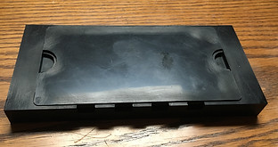
Fabricated Go No Go Gauge

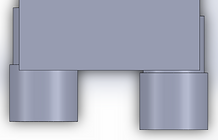
SolidWorks model of the Go No Go Gauge
Process
I created the gauge entirely in SolidWorks with the only two real important dimensions of the fixture being the depths of the slots on the left and right side. One side acts as the lower tolerance for the part while the other is the upper tolerance. I fabricated the main aluminum block structure of the fixture with a mill and worked with the machinists at Abiomed to narrow down on the tight tolerances of the side slots.
Results
To validate the fixture, I helped the manufacturing team perform a Gage R&R with incoming parts. When placing the incoming part into both slots, if the ledge is visible in both slots or obstructed in both slots, the part is out of tolerance and fails. The part is only in spec when the ledge is visible in one slot, the shallower slot. This fixture passed the Gage R&R and is used to measure incoming parts.

With both ledges obstructed, this part would fail inspection

With both ledges visible, this part would fail inspection
With one ledge visible, this part would pass inspection